Millworker
 Drawing Builder
A full drawing set from an assembly: one sheet per model, laid out by your sheet layouts.
- A saved assembly. Millworker tab → Drawing panel → Drawing Builder.
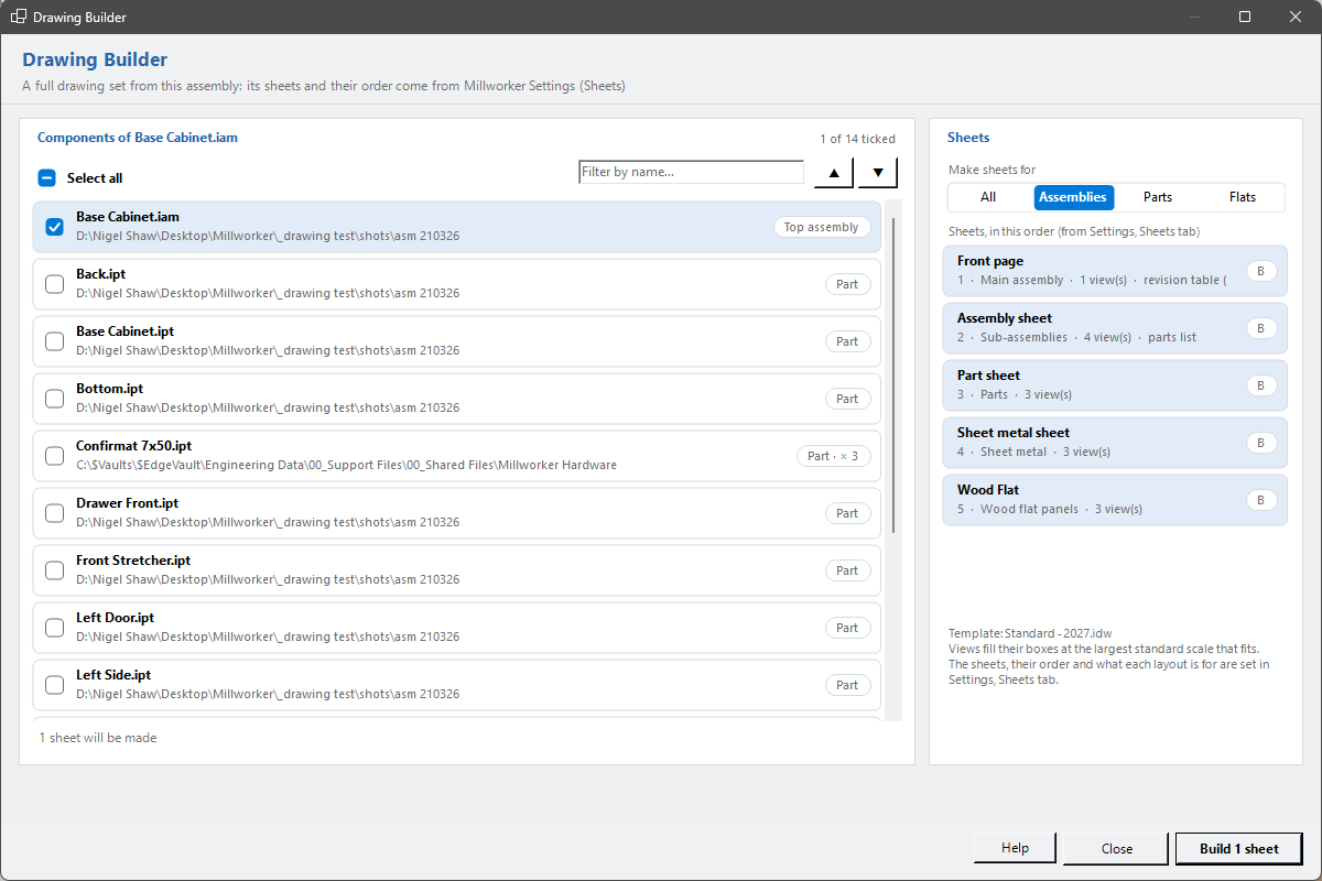
The list holds the top assembly, every sub-assembly and every part (Content Center and library parts are left out), with how many times each is used. Tick the ones that get a sheet, or use the quick select: All, Assemblies, Parts or Flats (sheet metal with a flat pattern, and wood flat panels). Change a tick and it becomes a custom selection. Models with a drawing already open start unticked.
Sheets, in this order: the list on the right shows the sheets the set makes. They are set once in Settings, Sheets tab: which layouts are ticked for the Drawing Builder, what each is for, and their order. There is nothing to pick here. The set goes down that list: every ticked model the first layout is for, then every model the second layout is for, and so on. A model gets one sheet for each layout that is for it. Rest the pointer on a sheet to see its layout.
- A model's first sheet is named by its part number; a further sheet adds the layout's name.
- Sheet metal uses the Parts layouts when there is no Sheet metal layout.
- A layout with only flat pattern boxes is used only for sheet metal with a flat pattern (and wood flat panels). Flats keeps to those layouts when there are any.
Build makes a new drawing from the template in Settings. A part (or sheet metal part) is drawn from its own shape, not the way it sits in its model: its largest flat face is the front, turned so the face's longest edge runs across (always landscape), and plan, side and iso follow from that. Each view group (a base view and the views projected from it) is placed in its boxes and given the largest standard scale that fits them all (1:2, 1:3, 1:4, 1:6, 1:8, 1:12, 1:16…; untick Round each view group down to a standard scale on the Sheets tab to fill the boxes exactly); sheet metal gets its flat pattern. The drawing is left open, not saved.
- A view set to hide its label is placed without one.
- An edge view (Front Right edge and so on) or a view with Look down gets its own camera: the front turned to the edge, then looked down on. The views projected from it follow it. A part keeps its largest face as the front, and a sub-assembly stands as in the top assembly.
- A Perspective view is made again on its own, looking the same way, after its group is placed. Nothing can be projected from it, so a view projected from it is placed on its own, still orthographic. A flat pattern is always orthographic.
- A layout's parts list box gives an assembly sheet a parts list, made from the sheet's first view. Its revision table box gives the sheet a revision table, for that sheet or the whole drawing, numbered and with its first row filled in.
- Anything that can't be done (a view that can't be aimed, say) is done the plain way and listed at the end. Each sheet, view and table placed is written to
drawing-builder.login Millworker's data folder.
Sub-assemblies are drawn as they stand in the top assembly. A CabinetCAD cabinet is built lying in its own file (Z up) and stood up in the list's assembly, so its sheet's front, plan and side are taken from the top assembly's own front, top and right where the cabinet stands there, not from the cabinet's file. Sub-assemblies that are the same (the same parts, the same sizes, in the same places), such as three identical cabinets each in its own file, get one sheet: the list shows the first with × 3 · also C2, C3.
Main assembly: the top assembly gets a sheet from every layout Used for Main assembly, in list order: the starters give it a front page and then a general elevation.
Wood flat panels: a curved panel flattened with Make Flat is listed as Curved panel · wood flat ✓ and gets a layout made for Wood flat panels (the starter has its front, side, iso and a flat pattern box with overall sizes). The flat pattern box shows the panel's wood flat. With no such layout, the Sheet metal layouts are used, then the Parts layouts. Flats in the quick select picks sheet metal and wood flat panels.
Order under each layout: the models come in the component list's order. Drag a row up or down (a blue line shows where it goes), or click a row and move it with ▲ and ▼.
Sheet layouts
In Millworker Settings, Sheets tab: the drawing template (borders and title blocks come from it; Inventor 2027 has its own, first set to Standard - 2027.idw in the EdgeVault templates folder) and the sheet layouts. Each layout has a size (ANSI B 17×11, C, D, or A4 to A0, landscape), what it's Used for (Main assembly, Sub-assemblies, Parts, Sheet metal or Wood flat panels), its title block and border from the template (or the template's own, or none) and its boxes. The thumbnail shows the template's real sheet under the boxes; the line under it sums the layout up, such as 2 view(s) · parts list · revision table (sheet).
Sheet order: the layout list is the order of the sheets in the drawing set. Drag a layout up or down (a line shows where it goes), or move it with ▲ and ▼; each row shows its place. Several layouts can be for the same thing: each makes its own sheet, in list order. New copies the picked layout, so a variation is quick to make.
Tick = used by Drawing Builder: untick a layout you keep but rarely use. It stays in Settings, marked not in builder.
Edit layout… (or double-click) opens the editor: add base views (any ViewCube direction, an edge view, or the flat pattern) and projected views; drag them to move, drag sides and corners to size. For the picked view:
- Show the view label: whether its label is on the sheet. A box without one says (no label).
- Add overall dimensions: its overall width (above) and height (to the right). Not on a perspective, edge or look-down view. The starter layouts have them on the front, plan, side and flat pattern views.
- Orthographic or Perspective, set on each view. A flat pattern, and a view projected from one, stays orthographic.
- The edge views (Front Right edge, Front Left edge, Back Right edge, Back Left edge) are the ViewCube's upright edges, level between two faces.
- Look down (0° to 25° in 5° steps) raises the eye so the top shows. Base views only; not for a flat pattern.
- The little cube in the picked base view's box shows how the view will look.
A projected view snaps in line with its parent beside, above or below it, or goes at a corner for an iso. Everything snaps to 5 mm. Until you save layouts of your own, the starter layouts (all B, 17×11) are used.
Parts list and revision table: + Parts list and + Revision table put a box for each on the sheet (blue and violet), one of each per layout. A parts list only goes on a Main assembly or Sub-assemblies layout. Drag the box where the table goes. Pick it to set:
- Style: from the template's styles, or the template's default.
- Snap tables to the border (on at first): the box snaps to the border's inner line (inside any zone strip, below a header strip) and to the top of the title block, and the real table goes tight against it on the side its box is nearest. Off, the table goes at its box.
- Revision table for Sheet (each sheet has its own) or Drawing (one for the whole drawing).
- Numbering (A, B, C or 1, 2, 3) and the first row description (FIRST ISSUE at first), put in the Description column. These two are shared by every layout.
The real table's size comes from the model, so the box only says where it goes: the table takes the corner of its box nearest the sheet's corner.